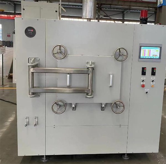
Box Furnace
Professional Powder Handling Solutions

Box Furnace
Engineered to provide precise temperature and atmosphere control, ensuring safe and effective processing of lithium compounds used in batteries and other applications.
REF. 001/814
Available in store
Product features
-
Equipment use location: indoor installation.
-
Operating temperature: RT~1250°C, rated temperature: 1350°C.
-
Furnace size: 850L×450W×300H mm, sagger size: graphite sagger 355×355×210mm (two rows stacked).
-
Furnace material: mullite polylight brick + 1260 type ceramic fiber.
-
Heating element: silicon carbon rod, jacket: ceramic protective sleeve.
-
Temperature control stability: ±1°C, controlled by intelligent program regulator, with PID parameter self-tuning function.
Number of temperature control points: 2 points, upper and lower separate temperature control, number of temperature control sections: 4×8 sections of heating curve, rated power: 40 Kw. -
Power supply: 380±5%V power supply, 50Hz.
-
Nitrogen/oxygen: high purity nitrogen/oxygen above 9.999%, supply flow ≥1.6m³/h.
-
Cooling water: clean water quality, water temperature preferably below 25°C, supply flow ≥0.1m³/h.
-
Thermocouple model: S type.
-
Air intake system: main air intake at the bottom, auxiliary air intake on both sides, flow meter control.
-
Exhaust system: 1 exhaust at the top, exhaust pipe ∅50, switch controlled by valve.
-
Furnace door and wiring chamber seal: water cooling + silicone rubber
-
Silicon carbide rods are used as heating elements to ensure continuous operation under nitrogen and argon conditions. The atmosphere control of the equipment is divided into pressure control and flow control. During use, the entire furnace is inflated and sealed, requiring the furnace to maintain a certain pressure, generally around 0.1 KPa. A 0-1 KPa micro pressure gauge is installed on the furnace body.
-
There are two air inlet positions in the furnace: Air Inlet Position 1: Air enters through a DN10 ceramic tube, which is longer than 250mm. The air inlet points are located at the upper and lower positions of the furnace. The air pipe is preheated through the furnace wall before entering the furnace. Multiple air outlet holes are placed on the tube to create a uniform cross-sectional air inlet. Additionally, the furnace bottom is equipped with a foot pad. Air Inlet Position 2: An air inlet hole is located on the furnace bottom support plate. The gas filled into the furnace passes through the insulation fiber at the bottom and enters the furnace through the air inlet hole in the support plate.
-
Air Inlet Pipeline: After the air inlet pipeline is installed outside the furnace, the air inlet position can be adjusted to either Air Inlet Position 1, Air Inlet Position 2, or both simultaneously using a ball valve.
-
Atmosphere control: The flow meter is equipped with two rotor flow meters in parallel with 0-20L/min and 0-5L/min.
-
The exhaust port is located in the middle of the furnace top, and exhaust gas is discharged through the exhaust pipe. The exhaust pipe is made of DN32 stainless steel 304 pipe, with an embedded ceramic tube containing more than 90% alumina. A valve is installed at the bottom to facilitate control of the exhaust flow.
-
The control system adopts an integrated design with the furnace body. An intelligent temperature controller is used, which receives signals detected by the thermocouple. The power adjustment board triggers the control power module, and an S-grade thermocouple, housed in a corundum ceramic tube, measures the temperature. The instrument features a PID parameter self-tuning function, providing control stability within 1°C. It also includes multiple alarm protection functions, such as a high-temperature upper limit alarm and a thermocouple failure indication.
-
The temperature control system of the electric furnace is installed separately in an independent control cabinet, which is splitted into two parts: the control panel and the power board.
-
The furnace door is sealed with a high-temperature resistant 350°C silicone rubber sealing ring, and is locked with a quick connection clamp. The furnace chamber is equipped with water cooling, and the user only needs to connect the water source to use it.
-
The furnace shell adopts a double-layer structure, the main color is beige and blue is the optional color. The furnace top cover plate and decorative plate both adopt a breathable plate hole structure.
Technical specifications
| Parameter name | Parameter value |
|---|---|
| Operating temperature (°C) | RT∼1250 |
| Rated temperature (°C) | 1350 |
| Furnace size (mm) | 850L×450W×300H |
| Sagger material | Graphite |
| Sagger size (mm) | 355×355×210 (two rows stacked) |
| Furnace material | Mullite poly light brick + 1260 type ceramic fiber |
| Heating element | Silicon carbon rod with ceramic protective sleeve |
| Temperature control stability | ±1°C, controlled by intelligent program regulator with automatic PID parameter. |
| Temperature control points | 2 independent upper and lower points |
| Temperature control sections | 4×8 sections heating curve |
| Rated power (kW) | 40 |
| Gas system | Flow meter |
| Atmosphere | Air, oxygen, nitrogen |
| Power supply | 3 phase, 380VAC, 50Hz |
| Thermocouple model | S type |
| Air intake system | Main air intake at the bottom, auxiliary air intake at both sides, flow meter control |
| Exhaust system | 1 exhaust at the top, exhaust pipe ∅50, switch controlled by valve |
| Furnace door and wiring chamber sealing | Water cooling + silicone rubber |